Transformer Water Spray design

Standard
for Water Spray Fixed Systems for Fire Protection
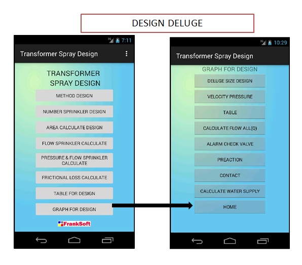
Appilcation For Android
Appilcation Download : Transformer Spray designhttps://play.google.com/store/apps/details?id=com.design.transformerspraydesign
ผม
Download : https://play.google.com/store/apps/details?id=com.design.transformerspraydesign
ผม
Download : https://play.google.com/store/apps/details?id=com.design.transformerspraydesign
The Standard for Water Spray Fixed Systems for Fire
Protection, formerly Water Spray Nozzles and
Extinguishing Systems, first prepared by the Committee on Manufacturing Hazards, was tentatively adopted in 1939, with final adoption in 1940. Subsequently, this standard was placed under the jurisdiction of the Committee on Special Extinguishing Systems, and a new edition was adopted in 1947. In 1959, the committee organization was further changed to place primary responsibility in the hands of the Committee on Water Spray, under the general supervision of the General Committee on Special Extinguishing Methods. In 1966, the General Committee on Special Extinguishing Methods was discontinued, and the Committee on
Water Spray was constituted as an independent committee. Revised editions were presented
in 1969, 1973, 1977, 1979, and 1982.

1. This standard provides
the minimum requirements for the design, installation, and system acceptance
testing of water spray fixed systems for fire protection service and the
minimum requirements for the periodic testing and maintenance of
ultra-high-speed water spray fixed systems.
2.* Water spray fixed systems shall be specifically designed to provide for effective fire control, extinguishment, prevention, or exposure protection
2.* Water spray fixed systems shall be specifically designed to provide for effective fire control, extinguishment, prevention, or exposure protection
3.* This standard shall
not apply to water spray protection from portable nozzles, sprinkler systems,
monitor nozzles, water mist suppression systems, explosion suppression, or
other means of application covered by other standards of NFPA.

4. Water spray protection is acceptable for the protection
of hazards involving each of the following groups:
(1) Gaseous and liquid flammable materials
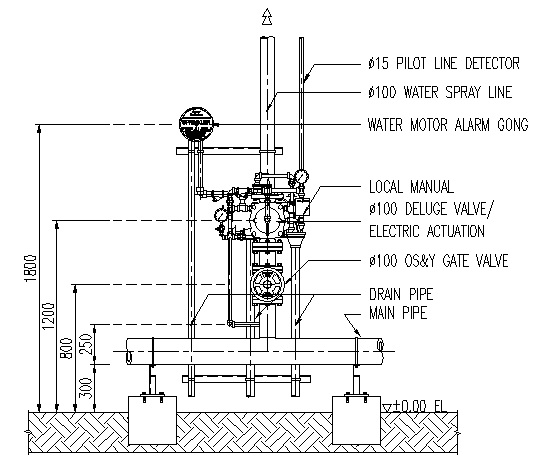
(2) Electrical hazards such as transformers, oil switches, motors, cable trays, and cable runs
(3) Ordinary combustibles such as paper, wood, and textiles
(4) Certain hazardous solids such as propellants and pyrotechnics
(5) Vapor mitigation
of hazards involving each of the following groups:
(1) Gaseous and liquid flammable materials
(2) Electrical hazards such as transformers, oil switches, motors, cable trays, and cable runs
(3) Ordinary combustibles such as paper, wood, and textiles
(4) Certain hazardous solids such as propellants and pyrotechnics
(5) Vapor mitigation


Appilcation Download : Transformer Spray design
Youtube Video


