Gas Fire Protection DesignFor Fire Supperssion System

Download Appilcation : Gas Fire Protection Design
Download Link:
Clean Agent Fire Extinguishing Systems
Gas Fire Protection is Gaseous fire suppression is a term to
describe the use of inert gases and chemical agents to extinguish a fire. Also
called clean agent fire suppression. These agents are governed by the National
Fire Protection Association (NFPA) Standard for Clean Agent Fire Extinguishing
Systems – NFPA 2001 in the USA, with different standards and regulations in
other parts of the world. The system typically consists of the agent, agent
storage containers, agent release valves, fire detectors, fire detection system
(wiring control panel, actuation signaling), agent delivery piping, and agent
dispersion nozzles. Less typically, the agent may be delivered by means of
solid propellant gas generators that produce either inert or chemically active
gas.
Fire suppression for Appilcation

Gas Fire Protection Design
1.
FM-200 = HFC-227ea ,Heptafluoropropane , CF3CHFCF3
2.
NOVEC-1230 = FK-5-1-12, Dodecafluoro-2-methylpentan-3-one ,CF3CF2C(O)CF(CF3) 2
3.
CO2 HIGH PRESSURE
4.
FE-13 = HFC-23 , Trifluoromethane , CHF3
5.
Inert Gas Design
IG-01= (ARGON)
= ARGON (100%)
IG-55 =
NITROGEN (50%) + ARGON (50%)
IG-100
(NITROGEN) = NITROGEN (100%)
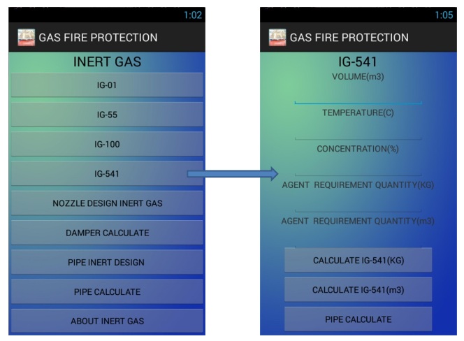
IG-541
(INERGEN) = NITROGEN (52%) + ARGON
(40%) + CO2 (8%)

Clean Agent Fire
Extinguishing Systems use by and guidance of those charged
with purchasing, designing, installing, testing, inspecting, approving,
listing, operating, and maintaining engineered or pre engineer clean agent
extinguishing systems, so that such equipment will function as intended
throughout its life.
Download Manual Gas Fire Protection
Design Link
FUNTION
APPILCATION WORK 121 FUNTION
FUNTION APPILCATION
1. METHOD FOR
DESIGN
2. NOVEC-1230
3. FM-200
4. INERT GAS
5. CO2 HIGH
PRESSURE
6. FE-13
7. TABLE FOR
DESIGN
8. GRAPH FOR
DESIGN
METHOD FOR DESIGN
1. CLASS DESIGN OF
NOVEC-1230
2. CLASS DESIGN OF
FM-200
3. CLASS DESIGN OF
FE-13
4. CLASS DESIGN OF
INERT GAS
5. CLASS DESIGN OF
CO2
6. OPERATION
DIAGRAM FM-200,NOVEC-1230 & FE-13
7. SCHEMATIC
DIAGTAM
8. CONTACT
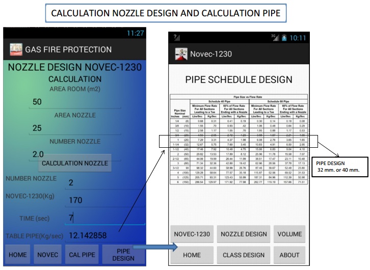
NOVEC-1230
1. NOVEC-1230
CALCULATE
2. NOVEC-1230
ABOUT
3. DESIGN
CONCENTRATION
4. NOZZLE DESIGN
NOVEC-1230
5. PIPE NOVEC-1230
CALCULATE
6. PIPE SCHEDULE
NOVEC-1230
7. TABLE FOR DESIGN
8. GRAPH FOR DESIGN
FM-200
1. FM-200
CALCULATE
2. FM-200 ABOUT
3. DESIGN
CONCENTRATION
4. NOZZLE DESIGN
FM-200
5. PIPE FM-200
CALCULATE
6. PIPE SCHEDULE
FM-200
7. TABLE FOR DESIGN
8. GRAPH FOR DESIGN
INERT GAS
1. IG-01
2. IG-55
3. IG-100
4. IG-541
5. NOZZLE DESIGN
INERT GAS
6. DAMPER
CALCULATE
7. PIPE INERT
DESIGN
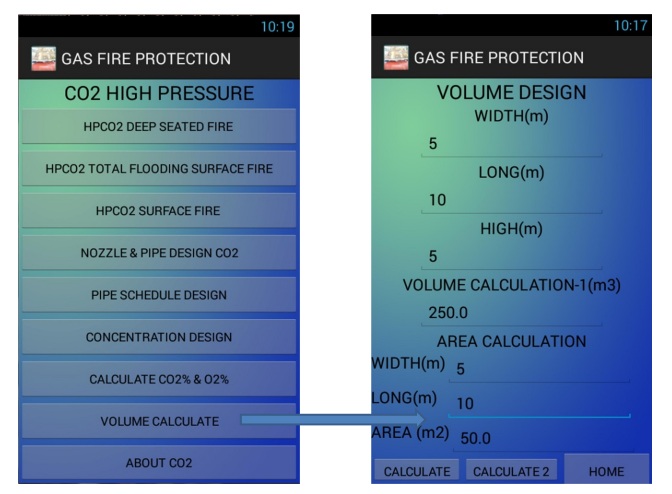
CO2 HIGH PRESSURE
1. HPCO2 DEEP
SEATED FIRE
2. HPCO2 TOTAL
FLOODING SURFACE FIRE
3. HPCO2 SURFACE
FIRE
4. NOZZLE &
PIPE DESIGN CO2
5. PIPE SCHEDULE
DESIGN
6. CONCENTRATION
DESIGN
7. CALCULATE CO2%
& O2%
8. VOLUME
CALCULATE
9. ABOUT CO2
FE-13
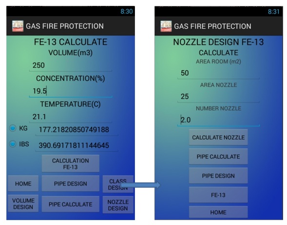
1. FE-13 CALCULATE
2. FE-13 ABOUT
3. DESIGN CONCENTRATION
4. NOZZLE DESIGN
FE-13
5. PIPE FE-13
CALCULATE
6. PIPE SCHEDULE
FE-13
7. TABLE FOR
DESIGN
8. GRAPH FOR
DESIGN
TABLE FOR DESIGN
1. TABLE PIPE
DESIGN OF NOVEC-1230
2. TABLE PIPE
DESIGN OF FM-200
3. TABLE PIPE
DESIGN OF FE-13
4. TABLE PIPE
DESIGN OF CO2 HIGH PRESSURE
5. TABLE PIPE
DESIGN OF IG-01
6. TABLE PIPE
DESIGN OF IG-55
7. TABLE PIPE
DESIGN OF IG-100
8. TABLE PIPE
DESIGN OF IG-541
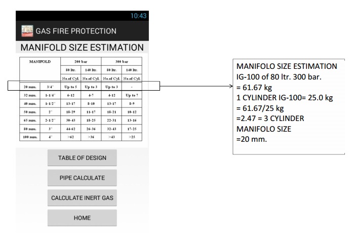
9. MANIFLOW SIZE
ESTIMATION
GRAPH FOR DESIGN
1. AVERAGE NOZZLE
PRESSURE NOVEC-1230
2. NITROGEN
TEMPERATURE & PRESSURE FM-200
3. MINIMUM DESIGN
CO2 CONCENTRATION
4. TEMPERTURE
& PRESSURE FOR CO2 CYLINEDERS
5. FE-13 PRESSURE/
TEMPERTURE CUREVE
6. ISOMETRIC
DIAGRAM OF IG-01
7. ISOMETRIC
DIAGRAM OF IG-100
8. ISOMETRIC
DIAGRAM OF IG-541
FUNTION APPILCATION WORK 121 FUNTION


Example Calculate & Design


Youtube Video